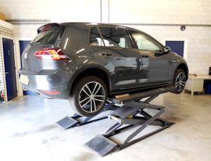
Recently, our helpdesk got a call from an installer who had some problems when installing a taximeter. For the required speed signal, he connected a Beijer CAN Interface (BCI) to the CAN-bus of the car. He already tried everything, but never succeeded in making the taximeter work. He wondered if the BCI was the problem.
 Step by step we went through all conditions for a successful BCI installation with the installer, but soon it appeared that he did everything the right way. The connections he made were consistent and the initialisation process was completed accordingly as well: the BCI recognized the car. Yet, the taximeter-speed wouldn’t increase if he started driving the car. Whilst the speedometer of the car did. When we went through all conditions for a proper functioning BCI with him, it appeared that the car was located on a lift bridge. Because the car couldn’t be replaced any time soon and they wanted to check on beforehand if the system functioned properly, the driven front wheels were released so they could ‘drive’ to check if the taximeter-speed would increase. But the taximeter-speed didn’t increase, despite the fact that the speedometer of the car did. When the car, after the conversation with our helpdesk, finally stood on its four wheels and they could actually drive the car, the taximeter did seem to function accordingly. Problem solved.
To clarify this situation, we will look at the factors that played a role. The most important factor is the value of the speed signal on the network of the car, the location of this value and the capacity of this value. To understand this, we have to go back to the origin of the speed signal in a car. In the basis, a speed signal always comes from the wheels in the form of analogue pulses that the ABS-unit receives from one or more of the wheels. Subsequently, the signal from one or more of the wheels (whether or not driven) is being converted to a digital value that is being placed on one or more CAN-busses of the car. The speedometer can for instance, only get offered the value of the left front wheel, but just as likely the one of the right rear wheel. Simultaneously, it’s possible that the speedometer only receives a calculated value that originates from the signals of multiple wheels. That simply depends on the way the car manufacturer devised it. Consequently, the speedometer will display a speed to the driver, based on the value it gets offered. And in the same manner, our engineers devised at which speed value the BCI functions best and which location/CAN-bus is most suitable for that.
And so it could happen that the speedometer receives its speed information through another CAN-bus than the BCI. However, this doesn’t necessarily have to lead to the upper mentioned situation. Namely the BCI could read the same speed value, if this is also present on the other CAN-bus. In that case, the speed of the taximeter could easily increase, despite the fact that only the driven wheels were turning. Nevertheless, in this specific case the BCI read another speed value (one that only increased with four turning wheels) through which the taximeter didn’t display a speed.
Conclusion: always check the operation of the after-market system after an installation when driving with four wheels on the ground.